Realsoft Graphics Oy |
Wire Tab
|
|
|---|---|---|
 |
Common Properties of Geometric Objects | 
|
Realsoft Graphics Oy |
Wire Tab
|
|
|---|---|---|
|
|
Common Properties of Geometric Objects |
|
![[Note]](../../../../../gfx/note.gif) |
Note |
|---|---|
| Bounding box handles do not show unless their drawing is enabled from the view popup menu. |
|
Hide Rotate Handle: Hides the object space rotate handle of this object.
|
 |
|
Hide Coordinates Handle: Hides the object space scale and translate handle of this object.
|
 |
|
Hide Rotate Handle in Edit Mode: Hides the rotation handle of this object in point editing mode. Some objects, such as the Subdivision Surface, display so many other handles that hiding the default handle may be necessary to avoid excessive handle wireframe. With the rotation handle, as well as the Coordinates Handle described below, you can edit the selected points in object's space. The handles are positioned in the average point of the selected points. Rotate handle drawing must be enabled from the view popup menu, otherwise the handles won't be drawn. |
 |
Hide Coordinates Handle in Edit Mode: Hides the scale/translate handle of this object in point editing mode. You can edit the selected points in the object space with this handle. Rotate handle drawing must be enabled from the view popup menu, otherwise the view window will not draw the handles.
Hide Geometry: Makes the actual object geometry (surface, curve, etc.) invisible in real time drawing. Handles and possible sub objects will be drawn normally.
No Shading: Forces wireframe drawing also in shaded OpenGL drawing.
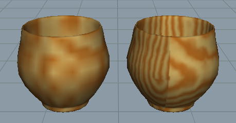
Vertex Colors: If set, colors from materials are evaluated per mesh vertex. This overrules Texture Quality setting - no texture bitmaps are used. This is sometimes the most suitable and quickest way to roughly show the surface colors.
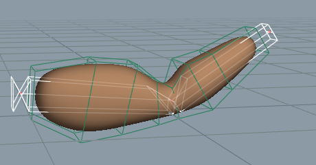
Draw Bounding Box Only: Hides the actual surface and shows only the bounding box of the object. Sometimes it is enough to see only the objects under editing using accurate geometric representation. Other objects can be drawn using simple reference boxes. Using a bounding box instead of accurate wireframe or shaded surface naturally speeds up model drawing and reduces visual complexity of a detailed scene, thus making editing the scene easier.
Draw when Selected: If set, object wireframe becomes visible only when the object is selected directly (not as a part of selected parent level). This is useful for example for material mapping objects, whose wireframe does not clutter the scene, but which become visible when it is time to adjust the size or proportions of the mapping.
Evaluate with Normal: When set, shader conversion to OpenGL textures computes surface normal. This gives more accurate result when shaders (or material maps such as the roll mapping) depend on the normal.
Show Name: If set, the object name is displayed on view windows.
Draw Only Profile: If set, only wireframe of sharp edges and object boundary is drawn. The option works best with dense wireframes.
|
Wire density: The density of wireframe mesh i.e. the density of wireframe curves drawn on surfaces. This setting has no effect on 1D curves. |
 |
|
|
 |
|
| Tags Tab |  |
Constructors |