Realsoft Graphics Oy |
Particle Objects
|
|
|---|---|---|
 |
Geometric Primitives | 
|
Realsoft Graphics Oy |
Particle Objects
|
|
|---|---|---|
|
|
Geometric Primitives |
|
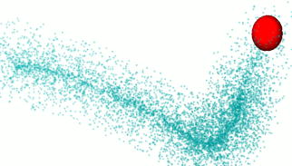
A particle object consists of a number of simple geometry items, such as points or lines. Despite of their simplicity, particles can create interesting rendering effects, thanks to the following reasons:
A particle cloud or flock can include a very large number of items.
Particle appearance can be customized using VSL materials.
Particle effects can be mapped on particles.
Particles can be rendered as scanline objects before ray tracing or in the post processing phase after ray tracing. Scanline particles can be controlled using a VSL material with a Scanline shader. Post particle rendering can be controlled using a Post particles shader.
![[Note]](../../../../../gfx/note.gif) |
Note |
|---|---|
| All usual surface attributes such as color, transparency etc. affect appearance of scanline rendered particles. The scanline system passes the result of its rendering to the ray tracer, which in turn evaluates the surface attributes when combining the scanline data with ray traced objects. Therefore, you can even bump map scanline particles by modifying the surface normal in a surface properties shader! |
|
Note |
|---|---|
| With a post particle shader, you can set and randomize may useful properties such as particle color, transparency, geometry points and diameters. |
All particle types have the following controls on the property window:
Age Definition - This selector defines, how the render engine sees the age of particles. The following three options are available:
Note that the gadget does not define the actual target channel for age definition. It must be selected from the Geometry tab. For example, age can be rendered directly to the Color channel.
Post Processing - If set, the particles are rendered in post processing phase of the rendering pipeline. This happens after ray tracing and is purely raster rendering, but distance and other channels can be taken into account. Post particles have only a limited interaction with ray traced items, but they are very quick to render. A Particle effect must be mapped to the particles, otherwise they does not render anything visible.
Scan Line - If set, particles are rendered by the scanline system before ray tracing, meaning that transparent particles show the items behind them, and reflective particles can mirror ray traced objects.
Ray Tracing - If set, particles are rendered as ray traced objects. This is usually the most memory intensive and slowest solution, but gives the most realistic results. 1D particles are rendered as spheres, 2D particles as cylinders or cones with rounded ends and 3D particles as elliptic spheres.
Count - The current number of particles
Max Count - The maximal number of particles. This limits how many items constructors such as emitter can add to the particle object.
Creation Rate - Defines how many particles constructors will add during the animation. Zero rate means that the particle count remains the same during the animation. A negative value means that when a particle dies, it is no longer regenerated, and particle count starts decreasing.
Properties - A list of attributes that can be assigned as a shared value common to all points or as a pointwise value.
Speed - Defines how fast particles move. The value is used when the Emitter construction is active.
Life Time - Defines how long particles live. When a particle dies, a new one is created to replace it. Therefore, the Life Time attribute has meaning only together with the emitter construction. You can select the type of age definition from the Rendering tab (relative 0..1 age, true age or the remaining life time).
Color - The usual diffuse color of particles.
Velocity - The motion vector of particles. Defines how much particle(s) move in one second.
Transparency - Transparency property for rendering.
Reflection - Reflectivity for rendering.
Alpha - The alpha channel value.
Fade - The Fade channel makes scanline particles translucent. Also some particle effects use the fade value for transparency control.
Illumination - Self illumination color. Used in scanline rendering.
Optical Thickness - A well known but in particle rendering only rarely useful optical property.
Scope - A material mapping attribute.
UVW Coordinates - Defines the position of each particle in the 'Emitter' and 'Surface' construction methods. This property is initialized to a random value when a construction is activated first time.
Other user channels - All custom channels of the Channels library are available here for rendering control purposes.
Common Value - The base (initial) value of the currently selected attribute. If 'pointwise' is not set, the gadget shows the common value of all particles. This control also defines the value range of life time and speed for recreated particles, when a particle constructor is active. When an attribute is changed to pointwise, the per point value is initialized using the common value.
Pointwise - Makes an attribute pointwise i.e. a value per particle point is allocated. Every particle can have its own private value for the attribute.
Point Value - The 'per point' value of the currently selected attribute. When set, the pointwise value overrules the Common Value.
Render Channel - The rendering engine channel to which a pointwise attribute is copied at rendering preprocessing time. This way all properties can be used to control particle shading.
Note: A pointwise value for all rendering channels (Color, Fade etc.) can be initialized using the map2Obj tool.
None - No particle construction applied. Particles can be freely moved around in 3D space.
Distribute over surface - The particles are placed randomly around the surface of the sub object. To use many objects, collect them into a single level.
Emitter - Particles are generated on the surface of the sub object with defined life time and velocity properties. New particles appear as old particles die. The following attributes control the behavior of emitted particles:
Life time randomness - Defines how much the life time of created particles varies. Value 1 will produce a totally random life time between zero and the object's common Life Time attribute.
Speed randomness - Randomizes the speed of emitted particles. If the value is zero, all particles have the same speed (defined by the common Speed attribute of the object).
Direction randomness - Randomizes the direction to which emitted particles travel. Value 1 will produce a totally random direction. Value zero will emit the particle to the exact surface normal direction of the creation point.
Position randomness - Randomizes the position of the particles to be created. If zero newly created particles are created on the surface of the emitter object. The bigger the value the larger the displacement.
Colorize - If set, the color of the sub object in the emission point defines the color of the emitted particle.
In addition to these three controls, also the common/pointwise properties of particles defined in the Geometry tab control the particle behavior. Common values define the range for randomization and pointwise values are used until the particle dies and a new one is created to replace it.
Filler - The particles are placed randomly inside the volume of the sub object. The sub object must define a solid volume; use analytic objects or freeform surfaces combined into a boundary surface solid.
A 1D particle renders in scanline as a round disk that is facing towards the camera.
Scanline particle location can be displaced using a 'Scanline shader' in a VSL material. The 'Coordinates' channel defines the position.
1D scanline particle object defines the following UV space (UV Coords channel): U runs from 0 at the middle point of a particle to 1 at the edge of the particle. V runs from zero at the first particle to 1 at the last particle.
The 'Size' property at the geometry tab defines the radius of particle discs.
In post processing, 1D particle drawing can be controlled by using the following channels in a 'Post particles' shader:
Color - particle color
Fade - particle transparency
Coordinates - position of a particle
V direction.X - the first sub channel defines particle radius
Ray traced 1D particles are rendered as spheres, unless the Ray trace as quadrangle option is set, in which case each particle is rendered as a flat square facing towards the camera. Quadrangles define also UV coordinates, which makes texturing easy.
A 2D particle object consists of a set of straight lines. Lines are suitable for modeling rays, fur etc.
2D particle specific properties:Particle ends can be displaced using a 'Scanline shader' in a VSL material.
2D particle object defines the following UVW space (UV Coords channel) in scanline drawing: U runs from 0 at the start point of a particle line to 1 at the end of the particle. V runs from zero at the center line of a particle to 1 at the edge of the particle. W runs from 0 at the first particle to 1 at the last particle.
2d particles have the following additional properties:
Diameter1 - The diameter of the start point of the particle in millimeters.
Diameter2 - The diameter of the end point of the particle in millimeters.
Length - The length of particles (in the current measuring unit).
In post processing, 2D particle drawing can be controlled by using the following channels in a 'Post particles' shader:
|
 |
3D particles define a full 3D coordinate system. They are therefore suitable for effects that require full orientation control in 3D space. The current post effect set does not require such control.
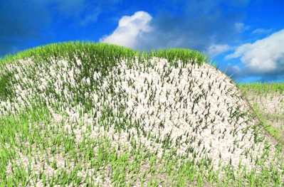
3D particles can be ray trace rendered as as spheres/ellipsoids or as rectangular planes. The latter alternative, available via the Ray Trace Rectangles option, is a very suitable feature, when a large number of UV textured rectangles is needed. 3D particle rectangles are rendered in a memory efficiet manner and they define UV coordinates. You can easily texture them to represent tree leaves etc.
The post processing control channels of 3D particles, available in a 'Post particles' shader, are:
Color - particle color
Fade - particle transparency
Coordinates - the middle point of a particle
U direction - a control point defining the first elliptic radius
V direction - a control point defining the second elliptic radius
Normal - a control point defining the third elliptic radius
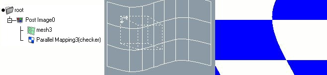
The Post Image is a special kind of particle object. It is classified as a particle object because the 'Render particles' post effect module renders it at the post processing phase. It is a level object, which can contain another geometry object. The sub object can be a rectangle, a NURBS mesh or another 2D geometry.
|
The geometry defines an image plane warping. Each point of the rendered image corresponds a point in the surface. The image plane can be colored by using a material which includes a 'Post particles' shader. By animating the material mapping or the sub geometry, you can create animated waves, warps and other interesting effects. |
 |
|
|
 |
|
| NURBS Surfaces |  |
Path Level |