
Modeling
NURBS Curves and Surfaces
Realsoft 3D implements Non-Uniform Rational B-Spline (NURBS) curves and surfaces in their full generality. When developing Realsoft 3D, various modeling tools were thoroughly analyzed and finally combined into the functionality of only three geometric tools: rectangle, circle and curve.
A model consisting of a number of NURBS meshes.
These three tools are easy to learn and allow the user to create all possible rectangular, circular and freeform objects. For example, to create a circular 'trim curve', simply activate the circle tool and set the 'Trim' option.
Typically NURBS surfaces are constructed from two or more NURBS Curves. For example, you can rotate a NURBS curve about another curve to get a banana.
Rotate a crossection
curve about an axis curve to create a banana.
Or create a set of NURBS curves and extrude them with desired beveling type, radius and extrusion depth.

Nurbs curves created
with the Font tool. The Extrude tool applied on the right.
The NURBS tool set includes tools, such as weld, extrude, sweep, rotate, cross sections, and more. It is also possible to trim surfaces, apply general Boolean operations between trim curves, and much more.
Rational Subdivision Surfaces
Realsoft has developed a technology called 'Rational Subdivision Surfaces' (briefly SDS). Realsoft 3D provides a comprehensive set of tools for SDS modeling.
SDS modeling typically starts from a simple basic shape, such as a cube. A cube renders as a smooth sphere. You can modify any vertex, edge or face of this object simply by dragging them with the mouse. In addition to this, you can create new faces through various SDS modeling tools, such as 'bevel', 'subdivide' and 'extrude'.
Create a cube, bevel
two edges, then extrude the new faces.
The weight point parameter of a SDS surface behaves exactly the same way as with NURBS surfaces. The stronger the weight, the stronger the point pulls the surface.
Three pyramids with different
apex weights.
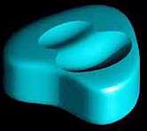
You can also control edge and face weights to round edges. For example, you can round the top and bottom faces of a cube to get a cylinder with rounded top and bottom lids. All the following three objects are defined by the same cube control polygon:

From left to right: a)
bottom face rounded. b) top and bottom faces rounded. c) all but one edges
rounded.
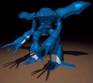
The following four images demonstrate a typical work flow for modeling with SDS surfaces. Modeling the following object takes approximately 10 seconds.
From left to right: 1)
A cube with rounded edges 2) top face subdivided and extruded 3) two vertical
edges beveled and extruded 4) two faces subdivided and extruded and rounding
radius defined for the extruded tentacles.
Metaballs
Metaball objects allow you to create organic shapes, water and many other interesting effects. Technically speaking, metaball object is based on a scalar field which is evaluated with a given 'iso value'.
Metaball, as the name suggest, is defined by one or more spheres. This results a smooth surface. However, Realsoft 3D allows material system to be used for defining scalar fields as well.
Solid Modeling 
A shape defined by two
metaballs and a fractal noise material.
Boolean operations can be applied between any kind of objects including NURBS meshes and metaballs. Boolean operations can be animated or modified afterwards easily using the construction history.
A boolean operation between
two NURBS surfaces.
For example, a hole in an object can be animated just like any regular object. Any number of surfaces can be combined to form a closed volume and then used in boolean operations as a solid object.
Naturally, a comprehensive set of analytical objects such as cone, cylinder and sphere are included. These objects are memory efficient and render quickly with a perfectly smooth surface.
Collision Detection System Integrated with Modeller's Tools
Drop an object onto a table to "squish" it, deform an object by moving it towards another object, etc.
Interactive collision
detection deformation.
Thanks to the new interface
design philosophy, collision detection is just an option for the transformation
tools. Activate the 'move' tool and set the option 'Detect collisions'.
Move objects and they will automatically deform because of the collisions.
It is this simple!
Transformation and Deformation Tools
Similar to the geometric creation tools, also the transformation and deformation tools were combined using the new design philosophy. As a result, there are only four basic tools: move, scale, rotate and skew, and four sets of options for these! With these tools, one can bend, twist and deform objects in any way. Previously a large number of construction, transformation and deformation tools has become three construction tools and four transformation tools.
Deformation Lattices
Any object can be used as
a deformation lattice. Deformation lattices can be used as modeling tools
or as animation tools.
Construction History
The construction tools create new objects from a number of simpler ones. Construction history means that these original objects are stored and can be modified afterwards in order to modify the actual constructed object. For example, when the user creates a candle stick by rotating a curve about an axis, the created object will contain the curves used for creating it in the first place. Another way to think of this is that the 'rotational surface' consists of two sub objects: a rotation axis and the cross-section curve. If the user is not satisfied with the shape of the surface, the desired construction history curve can be selected and modified. The surface is interactively modified as the curve is altered.
Particles
Particles are very useful in many modeling tasks. For example, they allow you to create hairs and fur.

Texture mapped 2D particles
Material properties of particles
can be defined similar to other geometric objects. Suitable VSL shaders
can be used to define color, transparency, shininess or any imaginable
property of particles.
 |
 |